
- Staff Editor
- Follow Me
- August 26, 2026
-
Electric vehicles are fundamentally changing automotive powertrain architecture. In an internal combustion engine vehicle, propulsion depends on an engine, multi speed transmission, fuel system, exhaust system and numerous mechanical subsystems. An electric vehicle replaces much of this complexity with an integrated electric drive system that combines the electric motor, power transmission, cooling interfaces, bearings, sensing elements and drive output into a compact assembly.
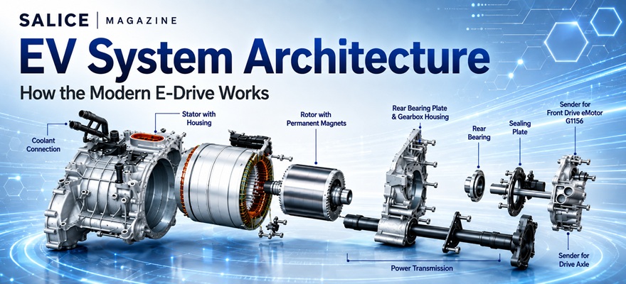
The illustrated architecture represents an integrated electric drive unit, or e-drive, shown in an exploded configuration. Its principal elements include the motor housing, stator, permanent magnet rotor, cooling connections, gearbox housing, bearings, sealing components and drive axle interface. Together, these components convert electrical energy into controlled mechanical torque and ultimately transmit that torque to the vehicle wheels.
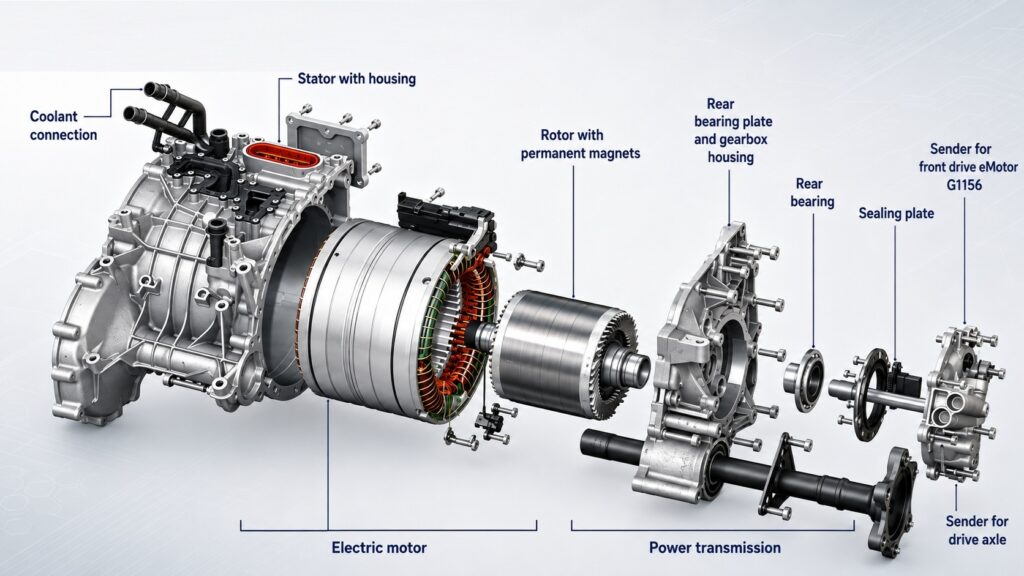
The electric vehicle system architecture shown in the illustration demonstrates how electrical, electromagnetic, thermal and mechanical technologies converge within a modern e-drive unit. The stator converts controlled electrical current into a rotating magnetic field, the permanent magnet rotor transforms that field into mechanical torque, and the transmission converts high speed motor rotation into usable wheel torque.
An important feature of modern electric vehicles is the increasing integration of motor, transmission and associated systems into a single module. An integrated e-drive offers several advantages as follows
Reduced vehicle weight
Smaller packaging volume
Fewer mechanical interfaces
Lower manufacturing complexity
Improved thermal management
Reduced assembly cost
Higher overall efficiency
Future electric drive systems are moving toward even greater integration, combining the motor, inverter, gearbox and control electronics into highly compact electric drive modules.
Electric Drive Housing
The outer aluminum housing forms the structural foundation of the electric drive system. It supports the electric motor, transmission components, bearings and associated interfaces while maintaining precise alignment between rotating components.
Because electric motors operate at high rotational speeds, dimensional accuracy and structural rigidity are critical. Even minor misalignment between the rotor, bearings and transmission can increase vibration, noise and mechanical losses.
The housing also contributes to thermal management and typically incorporates channels, mounting points and interfaces for cooling, electrical connections and vehicle integration.
Coolant Connection and Thermal Management
The coolant connections visible on the housing provide an interface between the electric drive unit and the vehicle’s thermal management system.
Electric motors generate heat primarily through electrical resistance in the windings, magnetic losses and mechanical friction. Excessive temperature can reduce efficiency, accelerate insulation degradation and limit the motor’s available power.
Liquid coolant is therefore circulated through or around the motor housing to remove heat. Effective thermal management allows the motor to maintain high continuous power output while protecting the windings, magnets, bearings and powertrain components. Thermal design is becoming increasingly important as manufacturers pursue higher power density from smaller and lighter electric drive systems.
Stator and Motor Housing
The stator is the stationary electromagnetic component of the electric motor. It consists of laminated electrical steel and conductive windings arranged around the inside of the motor housing. When alternating electrical currents are supplied to these windings by the vehicle’s power electronics, they create a rotating magnetic field. This rotating field interacts with the rotor and generates torque. The stator is one of the most important determinants of motor efficiency and performance. Its design influences:
Maximum torque
Power density
Thermal performance
Electrical efficiency
Noise and vibration
Manufacturing cost
Copper windings visible in the illustration form the electromagnetic interface through which electrical energy is converted into rotational force.
Permanent Magnet Rotor
Inside the stator is the rotor, identified in the architecture as a rotor incorporating permanent magnets. Unlike the stator, the rotor rotates with the motor shaft. When the stator generates its rotating magnetic field, magnetic interaction between the stator field and the permanent magnets produces torque.
Permanent magnet synchronous motors are widely used in electric vehicles because they can provide high efficiency, high torque density and strong performance across a broad operating range. The rotor may operate at several thousand revolutions per minute, meaning its mechanical design must withstand substantial centrifugal forces while maintaining extremely tight tolerances.
The air gap between the rotor and stator is particularly important. A smaller controlled air gap can improve electromagnetic efficiency, but sufficient clearance must be maintained to avoid mechanical contact.
Conversion From Electrical Energy to Mechanical Torque
The core energy conversion process occurs between the stator and rotor.
Electrical energy from the battery is first processed by a power inverter, although the inverter is not shown in this exploded mechanical architecture. The inverter converts battery direct current into controlled alternating current for the motor phases.
The sequence can therefore be represented as:
Battery → Inverter → Stator Magnetic Field → Rotor Rotation → Mechanical Torque
The motor controller continuously adjusts current, voltage and frequency according to accelerator demand, vehicle speed, traction conditions and efficiency requirements.
During regenerative braking, this process can operate in reverse. The motor functions as a generator, converting vehicle kinetic energy into electrical energy that can be returned to the battery.
Motor Shaft and Mechanical Power Transfer
Mechanical energy generated by the rotor is transferred through the motor shaft toward the power transmission section.
Because electric motors generally operate efficiently at much higher rotational speeds than vehicle wheels, motor speed cannot normally be transmitted directly to the axle. A reduction mechanism is required to convert high speed, lower torque rotation into lower speed, higher torque output suitable for vehicle propulsion.
This interface between the motor and transmission is one of the key integration points within the e-drive unit.
Gearbox and Power Transmission
The gearbox housing shown in the architecture forms the mechanical transmission stage of the system.
Most battery electric vehicles use a single speed reduction gearbox rather than the multi speed transmissions common in conventional vehicles. The reduction gears reduce motor rotational speed while multiplying torque before transmitting power to the axle.
A simplified relationship is:
High Motor Speed → Reduction Gear → Lower Wheel Speed + Higher Wheel Torque
This architecture contributes to one of the major advantages of electric powertrains: mechanical simplicity. However, gearbox engineering remains highly sophisticated. Gear geometry, lubrication, bearing design and housing stiffness must be optimized to minimize friction, noise and vibration while ensuring durability over the vehicle lifecycle.
Bearings and Rotor Support
The diagram identifies several bearing related components, including a rear bearing and bearing plate. Bearings support the rotating shaft and rotor while allowing them to rotate with minimal friction. They must also maintain precise alignment under changing torque, temperature and vehicle loading conditions.
Electric vehicle bearings face particular engineering challenges because electric motors operate at high rotational speeds. Bearing performance directly influences efficiency, durability and noise. Poor bearing alignment or lubrication can produce vibration, mechanical wear and premature drive unit failure.
Drive Axle Interface
The final stage of the illustrated architecture connects the power transmission to the drive axle.
After the gearbox reduces motor speed and increases torque, mechanical power is transmitted toward the wheels through the axle system. Depending on vehicle design, a differential may distribute torque between the left and right wheels.
The complete propulsion path can therefore be summarized as:
Electrical Energy → Motor → Rotor Shaft → Reduction Gearbox → Drive Axle → Wheels
This compact energy path is one reason electric powertrains can achieve significantly higher drivetrain efficiency than conventional combustion engine systems.
As EV technology advances, the competitive focus will increasingly shift toward higher power density, improved thermal efficiency, reduced weight, lower material usage and deeper integration of the motor, inverter and transmission. The electric drive unit is therefore not simply a replacement for the combustion engine, it is becoming one of the defining engineering platforms of next generation mobility.