- Staff Editor
- Follow Me
- February 15, 2025
-
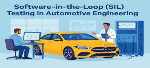
Example-1 : HIL Testing – Anti-lock Braking System (ABS) Validation
To better understand how Hardware-in-the-Loop (HIL) testing works in practice, let’s dive deeper into an example involving the validation of an Anti-lock Braking System (ABS) in a vehicle. ABS is a critical safety feature that prevents wheels from locking up during braking, ensuring vehicle stability and control. HIL testing allows engineers to rigorously test the ABS Electronic Control Unit (ECU) under a wide range of simulated conditions without the need for physical prototypes or real-world driving. Following are the key steps in the testing.
Define Test Objectives
The goal is to validate the ABS ECU’s ability to prevent wheel lock-up under various driving conditions, such as icy roads, wet surfaces, or sudden braking.
Specific test scenarios might include:
1. Braking on a dry road at high speed.
2. Braking on a wet or icy surface.
3. Sudden obstacle avoidance with hard braking.
Develop Simulation Models
a. Test engineers create a vehicle dynamics model that simulates the behavior of the car, including wheel speed, brake pressure, and road-tire friction.
b. A road model is developed to emulate different surface conditions (e.g., dry, wet, icy).
c. A sensor model simulates the signals from wheel speed sensors, which the ABS ECU uses to detect wheel lock-up.
Set Up Hardware
The ABS ECU (the hardware under test) is connected to the HIL simulator. The simulator includes:
a. Real-time processors to run the vehicle and road models.
b. Signal conditioning units to interface the ECU with the simulator.
c. Actuators to simulate brake pressure and wheel speed feedback.
Run Test Scenarios
The HIL simulator runs the predefined test scenarios in real time. For example:
Scenario 1: The vehicle is driving at 100 km/h on a dry road, and the driver applies sudden braking. The simulator sends wheel speed signals to the ABS ECU, which adjusts brake pressure to prevent lock-up.
Scenario 2: The vehicle is on an icy road, and the driver brakes moderately. The ABS ECU must detect reduced friction and modulate brake pressure to maintain traction.
The simulator can also introduce faults, such as a failed wheel speed sensor, to test the ECU’s fault-handling capabilities.
Analyze Results
During the tests, engineers monitor key parameters such as:
-Wheel speed and brake pressure.
-Vehicle deceleration and stability.
-ECU response time and decision-making.
Data is logged and analyzed to ensure the ABS system performs as expected under all conditions. Any deviations or failures are investigated and addressed.
Real-World Example: Bosch ABS system and HIL Testing
Bosch, a global leader in automotive technology, has been at the forefront of developing and validating advanced safety systems, including Anti-lock Braking Systems (ABS). To validate the performance and reliability of their ABS systems, Bosch extensively uses Hardware-in-the-Loop (HIL) testing during the development process.
Example-2 : HIL Testing: Testing an Adaptive Cruise Control (ACC) System
Adaptive Cruise Control (ACC) is an intelligent system that automatically adjusts vehicle speed based on the surrounding traffic. It uses radar, cameras, and LiDAR sensors to detect vehicles ahead and maintain a safe following distance. Before deploying ACC in real-world vehicles, it must be rigorously tested under multiple scenarios, including normal driving, sudden braking, and sensor failures.
HIL Testing Setup
The HIL test bench for ACC testing consists of:
Real ECU & Software: The actual ACC Electronic Control Unit (ECU), loaded with the latest software, is placed in the test environment.
Sensor Simulators: Instead of real world sensors, HIL testing simulates radar, camera, and LiDAR data, feeding them into the ECU.
Traffic Scenario Simulators: A real-time vehicle simulation model replicates road conditions, including multiple vehicles, pedestrians, and environmental factors.
Actuator Feedback: The HIL system mimics the brake and throttle signals, sending realistic feedback to the ECU.
Fault Injection System: Engineers can introduce sensor malfunctions, bad weather conditions, or communication failures to check how the ACC system handles them.
Test Scenarios and Validation Using HIL
Scenario 1: Normal Highway Driving
The HIL system simulates a highway with moderate traffic flow.
The ACC ECU receives radar and camera data, adjusts speed based on the leading vehicle, and ensures smooth acceleration and braking.
Scenario 2: Sudden Braking by Lead Vehicle
The simulation introduces a vehicle that suddenly brakes in front of the test vehicle.
The ACC system must detect this and immediately apply the brakes to avoid a collision.
Engineers analyze braking response time and safe stopping distances.
Scenario 3: Cut-In Vehicle Maneuver
A new vehicle suddenly merges into the lane at a close distance.
The ACC ECU must detect the lane change and adapt speed accordingly.
Scenario 4: Adverse Weather Conditions (Rain, Fog, Snow)
The HIL setup alters sensor data to simulate foggy conditions where cameras have reduced visibility.
Engineers evaluate how the ACC ECU switches to alternative sensors (radar, LiDAR) for better accuracy.
Scenario 5: Sensor Failure or Communication Loss
The test injects radar sensor failure or CAN bus communication delay.
The ECU should recognize the issue and alert the driver while switching to fallback systems.
Why HIL Testing is Critical for ACC Development?
Real-World Accuracy Without Real-World Risk – Engineers can replicate dangerous driving conditions safely in a controlled lab environment.
Faster Development & Reduced Costs – No need for expensive full-vehicle testing on test tracks until the system is well-validated.
Automated & Repeatable Tests – Scenarios can be run multiple times with consistent test conditions.
Regulatory Compliance & Safety Validation – HIL testing helps validate ISO 26262 functional safety requirements for automotive software.
Real-World Example: Tesla’s Autopilot and HIL Testing
HIL allows Tesla’s software engineers to simulate millions of miles of driving before real-world testing, significantly accelerating software deployment and updates.
Tesla uses HIL testing extensively to validate Autopilot features, including:
Adaptive Cruise Control
Automatic Lane Keeping
Collision Avoidance